

How Are Commercial Induction Cookers Made?
10/21/2026
Estimated reading time: 2 minutes

This article follows a typical commercial induction cooktop manufacturing process, drawing on ATRX’s published manufacturing information to explain material preparation, fabrication, component production and selection, and final assembly. If you are assessing a factory’s manufacturing capabilities or want to understand the work behind a finished unit, it will help you see which parts the factory makes, which it purchases, and what needs attention during assembly. The exact configuration depends on the model.(ATRX is a commercial induction cooker manufacturer, and the process described below reflects how we build our units. To learn more about the company and its product range, visit the ATRX homepage. You can also browse our full range of commercial induction equipment.)
What Materials and Components Are Needed Before Production?
Stainless Steel Sheets and the Glass-Ceramic Panel
ATRX prepares the stainless steel sheets for the cooker housing according to the approved model drawings. The material list specifies the stainless steel grade, sheet thickness, and dimensions required for the body panels and frame.
The glass-ceramic panel is purchased as a finished component. Before it is sent to assembly, ATRX checks that its size and shape match the housing opening and heating area and that its edges are intact. The factory fabricates the stainless steel housing; it does not cut the glass-ceramic panel.
Components for Heating, Control, and Cooling
Beyond the housing materials, the factory needs the components that make the cooker work. Our production line overview describes preparing structural parts, heating components, and electrical control components separately before sending them to final assembly. They fall into the following groups.
| Function | Main Components | What They Do |
|---|---|---|
| Heating | Induction coil assembly, power devices, and matching resonant capacitors | Work with the power circuit to create the alternating magnetic field needed for heating |
| Control | Control board, control panel, and sensors for temperature and other operating conditions | Receive user commands, monitor operating conditions, and control operation |
| Cooling | Fans, heat sinks, and any air duct components used in the design | Remove heat generated by power devices and other components |
Wires, Terminals, and Fastening Screws
These small items need to be prepared in advance too. Power wires carry current; signal and sensor wires carry information. Their requirements differ. Material preparation focuses on three things:
- Where each wire will be used. Check the conductor cross-sectional area, insulation voltage rating, and temperature rating.
- Which wire and connection each terminal fits. Check the compatible wire size, insulation outer diameter, connection type, and rated operating conditions.
- Which component each screw secures. Prepare the correct diameter, length, thread, and any required washers for each location.
Screws are particularly easy to treat as interchangeable. A screw may thread into a hole without clamping the part securely. One that is too long may extend into a nearby component or wire. Fasteners for brackets, circuit boards, and covers therefore need to be prepared separately and used in their assigned locations at the assembly station.Once the materials and components are prepared, the next stage is fabricating the housing. To see how material preparation fits into the whole workflow, you can read our 【commercial induction cooker production line】 overview.
How Is the Housing of a Commercial Induction Cooker Made?
Cut and Bend the Steel Sheets to Match the Drawings
The housing begins as flat sheet metal. Production staff first check the sheet metal flat-pattern drawings for part outlines, bend lines, mounting holes, and ventilation openings. Our housing fabrication overview shows the factory’s laser cutting, CNC punching, and bending equipment. Each part goes through the processes it needs.
Once the outlines and holes have been cut, the sheets are bent at the specified locations. This forms features such as sidewalls and bottom flanges. Openings for the control panel, fans, and bracket mounting holes also need to be made at this stage so the components can be fitted later.
P.S. If you’re interested in taking a closer look at the cutting stage, you can also see our commercial induction cooker laser cutting process, which explains how the flat sheet metal parts are cut before bending.

Weld the Housing and Finish the Seams and Edges
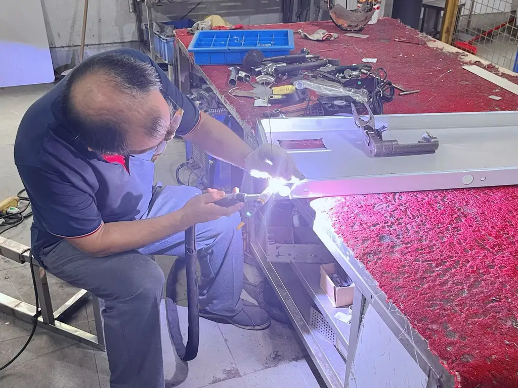
After bending, the parts are aligned and held in position to match the housing structure. The required joints are then welded. Covers and other parts that need to be removed later usually retain the screw connections shown in the drawings. The entire housing is not welded shut.
The welds need to join the parts securely while keeping heat distortion under control. After welding, workers check the housing for distortion and look for changes around mounting openings and joints. They also check that the top frame and covers still fit. A neat-looking weld does not tell you whether these dimensions are right.

Next, any welds that need finishing, cutting burrs, and sharp edges are addressed. Protrusions and edges that could cause cuts need to be removed, but grinding has its limits. Smoothing the surface must not thin the weld needed to hold the joint. Once this work is complete, the housing can move to the next assembly station.
How Does ATRX Make and Assemble the Main Components?
ATRX makes the control board and induction coil in separate production areas. It also prepares the cooling module for the specific cooker model. Each component is checked before it reaches final assembly.
Assemble and Test the Control Board in the PCB Cleanroom
ATRX assembles commercial induction cooker control boards in its PCB cleanroom. The ATRX PCB assembly process includes:
- Placing surface-mount components and soldering them by nitrogen reflow.
- Checking component position and visible solder joints with online AOI.
- Inserting through-hole components by hand and completing the joints by wave soldering.
- Inspecting the finished board, then running electrical and powered functional tests.
P.S. If you’re interested in seeing how the control board is assembled and tested in more detail, you can read our commercial induction cooker PCB assembly guide.

Wind and Inspect the Induction Coil for the Cooker Model
ATRX winds the induction coil on a programmable automatic winding machine. The turn count, wire spacing, and tension are preset for the cooker model and power level. After winding, the coil is fixed and cured, then checked for dimensions and electrical values before it is released for final assembly.

Assemble and Test the Cooling Fan Module
Cooling fans are purchased components. ATRX matches the fan model, voltage, connector, and size to the control board and cooker model, then fits the wiring harness and connector.

Workers check connector seating and polarity, then run the fan to confirm its speed and airflow. Vibration and unusual bearing noise are also checked before the module is released to final assembly.
How Is a Commercial Induction Cooker Assembled Step by Step?
Once the housing and components are ready, final assembly can begin. The steps below cover the brackets, electrical and cooling components, coil and cooking surface, wiring, and enclosure closure. The actual workstations vary with the model, power level, and order requirements. Some assemblies may also be completed outside the housing before being installed as a unit.
We have specially produced a complete assembly video of our ATRX product. You can first watch the video, and then I will explain it step by step to you.
Secure the Brackets and Component Mounts Inside the Housing
Brackets and mounting points are installed first so the later components have fixed locations. Using the drawings, assembly staff locate the coil support, circuit board mounts, and cooling assembly positions, then secure them after checking their orientation and hole alignment.
At this station, the mounting points need to line up with the component holes, and the areas around the brackets need enough space for the specified wiring and assembly work. An empty housing is easier to inspect and adjust. Once the boards, coil, and harnesses are installed, moving a bracket may require earlier work to be taken apart.
Install the Circuit Boards, Power Modules, and Cooling Components
The circuit boards are fixed to their mounting points with supports and any required insulating parts, keeping the back of the board from making unwanted contact with the metal housing. Depending on the workstation arrangement, the power devices and heat sink may be assembled as one unit before being installed in the housing.
The contact surfaces between the device and heat sink need to be clean. The specified thermal interface material and insulating parts are then fitted, and the assembly is tightened according to the device requirements. This contact affects heat transfer. The required material thickness and screw torque should come from the installation requirements for the specific package. One value should not be applied to every module.
After the fan and air duct parts are installed, check the airflow path and outlet. Harnesses must not block the fan. Nearby components and covers also need to leave room for the cooling path. The PCB and cooling assembly process information includes checks for airflow direction, connectors, and cooling clearances. The heat sink receives the heat, and the fan carries it away. Both need to be installed correctly.
Secure the Coil Assembly and Install the Cooking Surface
After placing the coil assembly on its support, align its center and orientation, route the leads, and then secure it. The gap between the coil and cooking surface is controlled by the supports, locating features, or measurement requirements specified in the drawings. The correct distance varies with the coil, cookware, and circuit combination, so one mounting distance cannot be applied to every model.
The cooking surface is then installed on its designed supports and secured with the specified fasteners and, where required, sealing materials. If the panel does not sit level, check its dimensions and support positions. Tightening the screws harder is not a substitute for correcting the fit. Fasteners also need to stay clear of the coil and its leads.
The production line assembly information includes coil positioning, insulation, and spacing parts. This station needs a combined check: the coil center should align with the heating area, and the relative position should meet the requirements. A panel that fits does not by itself prove that the coil below it is correctly positioned.
Install the Control Panel and Connect the Wiring
After the control panel is secured in the housing opening, connect the power, control signal, and sensor wires according to the wiring diagram. Port labels, harness markings, and the diagram should match. Even when two plugs have the same shape, their destinations still need to be confirmed.
The harnesses also need to be routed during wiring:
- Connect each plug to the correct port and confirm that it is fully inserted and locked.
- Route the harness along the specified path. Secure it where required and protect it where it passes through sheet metal.
- Leave the specified amount of slack so the harness is not pulled tight, pressed against a sharp edge, or brought into contact with a fan blade.
- Complete the protective earth connection at the designated grounding point. An ordinary structural screw cannot automatically serve as an approved grounding point.
The PCB assembly process also checks connector seating and polarity. During complete-unit wiring, the paths need to be checked from end to end: which board the panel connects to, which port receives each sensor, and where each wire is meant to go.

Check Wiring and Component Positions Before Closing the Housing
Before the cover goes on, the terminals, screws, and harnesses are still visible, so the assembly can be checked one more time. Confirm that no connector has been missed, every component is secure, the cover will not pinch a wire, and no screw or cut-off wire has been left inside.
Grounding deserves a separate check. A recall report published by RV News on October 2, 2023 said that certain Tiffin motorhomes had 240 V induction cooktops that may not have been grounded. The report identified a potential shock risk if wiring short-circuited and described adding a grounding connection to a metal junction box as the remedy.
That recall concerned a specific motorhome configuration and should not be generalized to all induction cookers. For manufacturing and assembly, it shows why protective grounding needs its own check after the power wiring is connected. Confirm the grounding point and connection before closing the housing, then verify electrical continuity through the applicable tests.
| What to Check Before Closing the Housing | What to Look For |
|---|---|
| Plugs and terminals | Are the connections correct and fully seated? Is anything left disconnected? |
| Brackets and component mounting | Are all mounting points complete? Is any component loose or out of position? |
| Harnesses and pass-throughs | Are the harnesses secured and protected? Could the cover pinch them? |
| Internal cleaning | Are there any loose screws, wire ends, or other foreign objects inside? |
After these checks, install and secure the outer cover and other panels. Check the seams, connections, and ventilation openings once more. At this point, the sheet metal and components have become a complete cooker. The production process still includes functional, safety, and performance testing. Closing the housing finishes assembly; the unit can be released only after it passes the required tests.
About the author

ATRX Team| 18 Years Commercial
Induction Cooker Manufacturer in China
Induction Cooker Manufacturer in China
Related Posts

Portable Induction Hobs vs Built-in Cooker: Which Is Right for You?
10/26/2026
How ATRX Handles OEM Custom Orders for Commercial Induction Cookers
10/24/2026

Commercial Induction Cooker Operating Instructions
10/23/2026

What Parts Are Typically Found Inside a Commercial Induction Cooker?
10/23/2026

Gas vs Infrared vs Induction: Efficiency, Cost & Cookware
10/22/2026

Commercial Induction Cooker Maintenance: 5 Tips to Extend Its Service Life
10/22/2026

How ATRX Controls the Quality of Commercial Induction Cookers: From Incoming Inspection to Final Quality Inspection
10/22/2026
How Are Commercial Induction Cookers Made?
10/21/2026

Should a Hot Pot Restaurant Choose an Induction Cooker or a Gas Stove?
10/21/2026

How Much Electricity Does a Commercial Induction Cooker Use
10/20/2026