How ATRX Built Its Commercial Induction Cooker Production Line
06/19/2026
Estimated reading time: 3 minutes
This article pulls apart how a commercial induction cooker production line doing 3,000 units a month got built from nothing. You’ll see the full decision chain — how the numbers were set, why specific equipment was picked, where things went wrong, and what real clients said after walking the floor. If you’re building your own line or sizing up a supplier, this gives you a concrete framework to work with.
IN THIS ARTICLE
How We Built a Production Line from Zero
Working Backwards from Monthly Output to Workstation Count
Most people think building a line starts with buying machines. It doesn’t. It starts with one number: how many units need to ship each month.
When ATRX kicked off this project, monthly capacity got locked at 3,000 units. That single figure drove every decision after it. A Southeast Asian client once asked our line manager during a factory visit: “How did you decide to go this big?” Simple — we added up signed contracts and forecasted demand. No guessing involved.
Here’s how 3,000 units per month shaped the line:
Assembly workstations: 16.
Derived from how long each process step takes. One fewer station and flow speed drops below target.
Testing workstations: 8.
Burn-in and power calibration run slower than assembly. Fewer stations here means the whole line backs up. We only finalized this number after a trial production run and one round of adjustment.
Minimum floor space: 1,200 square meters.
Workstations plus material staging plus room for a future parallel line — can’t go below this.
Equipment Configured at Each Stage
What’s on the Floor and How It’s Arranged
This commercial induction cooker production line sits in Dongguan. Total factory footprint: about 20,000 square meters. Sheet metal cutting through to final shipment — every key step happens in-house. Nothing gets farmed out. Nothing crosses to another facility.
The line breaks into four zones, arranged by process flow. Material comes in one end. Finished goods leave the other.
Sheet Metal Processing — Front of the Line
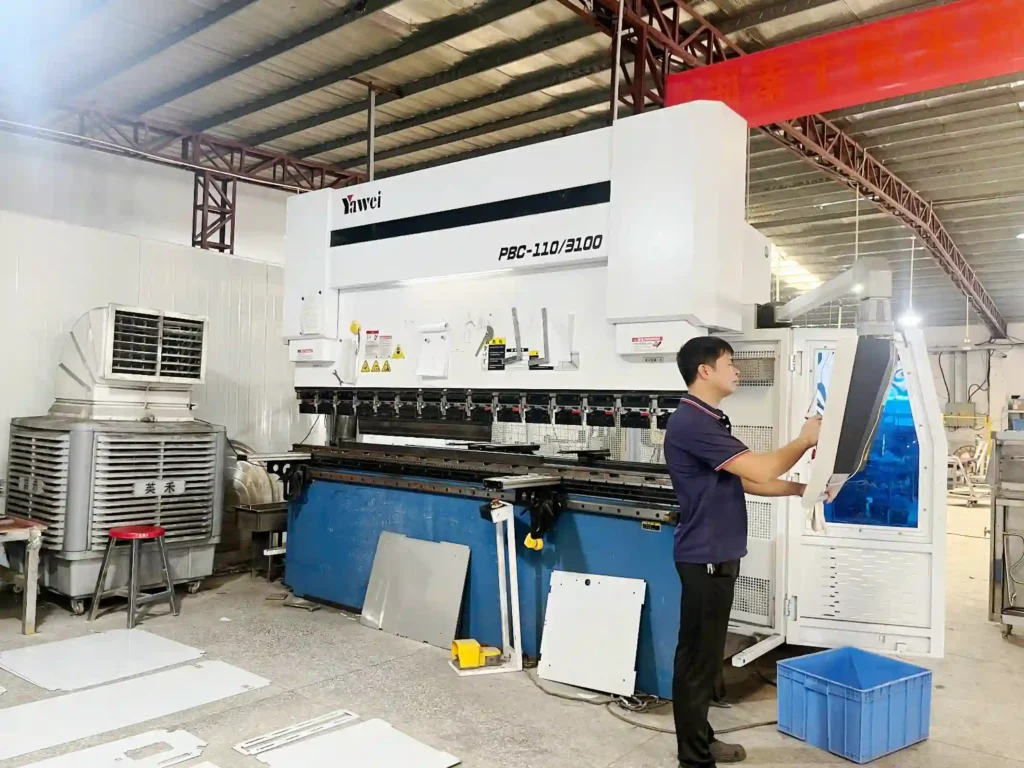
First up: a laser cutting machine. It takes full sheets of 304 stainless steel and cuts them into top panels, side panels, and bottom plates following CAD drawings. Cut pieces go straight into a CNC press brake. The machine bends flat steel into 3D structural parts using programmed pressure and angles.
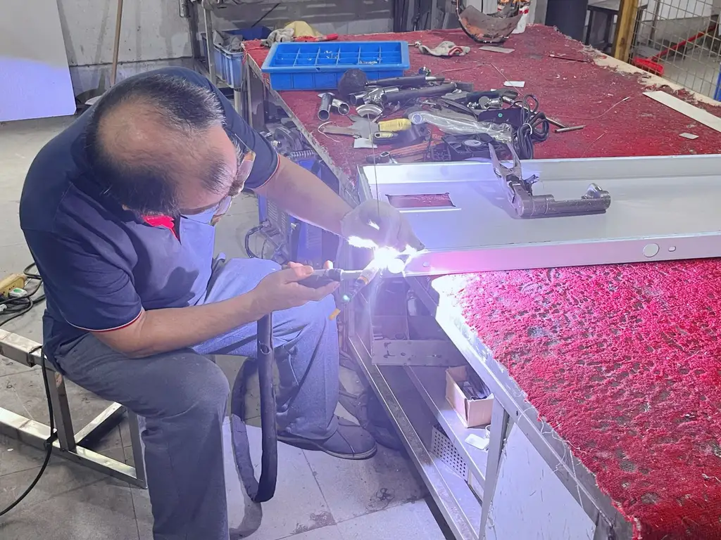
Next come welding stations. Certified welders join the bent pieces into complete enclosures per WPS specs. Last stop in this zone: a grinding and polishing bench. Weld spatter and burrs get removed. Only then is the shell considered finished.
Two precision numbers in this zone matter a lot downstream — cutting tolerance of ±0.1mm and punch positioning of ±0.03mm. These directly control how well the final unit seals and dissipates heat. For a deeper look at how these sheet metal steps affect finished product quality: Commercial Induction Cooker Laser Processing and Sheet Metal Forming Explained.
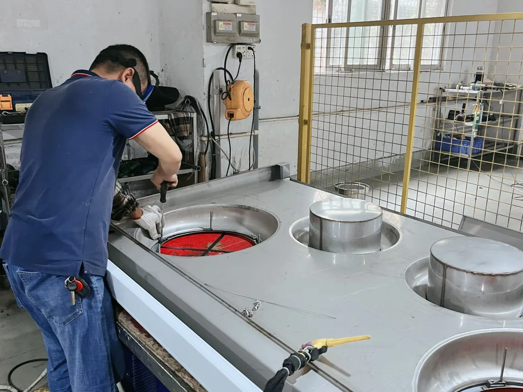
Coil Winding — Running Parallel to Sheet Metal
The key machine here is a programmable automatic winder. Turn count, wire spacing, tension — all preset in the program. The machine winds litz wire into flat coil discs layer by layer, then epoxy resin gets poured in and cured.
Different power levels get different parameters. Operators load material and unload finished coils. They don’t touch settings.
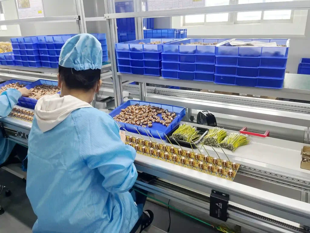
PCB Assembly — Dedicated Clean Room
This is the tightest-controlled area on the whole line. Particulates stay below 100 per cubic foot. Positive-pressure air, air showers at entry, and real-time particle counters run non-stop.
The induction cooker PCB assembly flow inside runs as a single straight line: SMT high-speed pick-and-place → ten-zone nitrogen reflow oven → AOI optical inspection → manual DIP insertion (with anti-static workbenches and visual guides) → wave soldering → exit-end AOI plus visual check. Boards move between stations on track conveyors. They never touch the floor. They’re never exposed to outside air.
For the full breakdown of each station’s controls — reflow temperature profiles, AOI logic, how IGBT solder quality gets locked board by board — that’s covered separately: Commercial Induction Cooker PCB Assembly Full Process Explained.
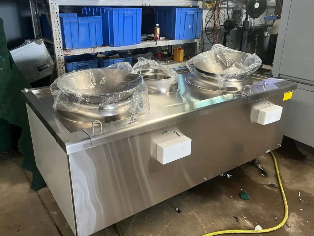
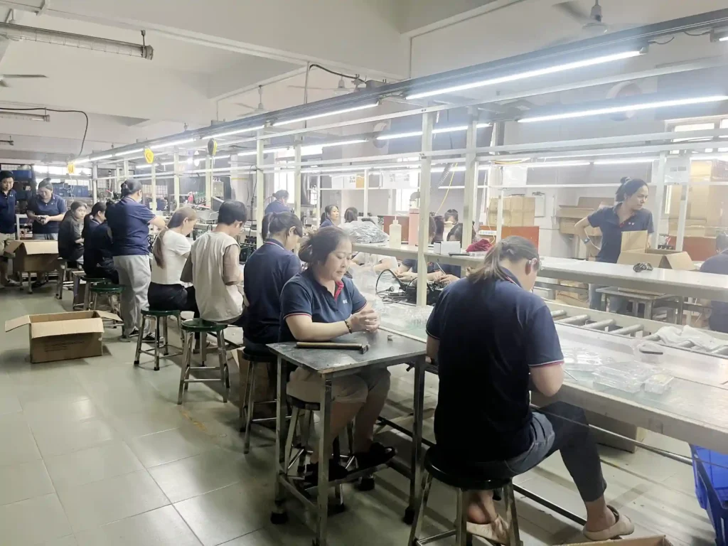
Final Assembly and Testing — End of the Line
Assembly runs as a station-based flow line. Each workstation has fixed jigs, a standard operation diagram on the wall, and specified torque values. The sequence: coil installation → IGBT module and heatsink mounting → main control board insertion → fan installation → wire harness routing.
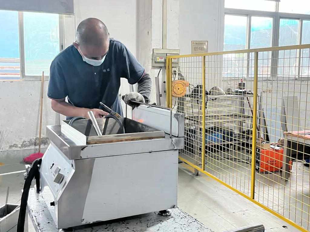
The flow line connects directly into the power test station and burn-in area. The burn-in zone is big — rows of test benches running finished units at full power simultaneously.
The overall induction cooker factory layout follows one rule: three upstream branches run in parallel (sheet metal, coils, PCBs — each on its own track), then merge into a single straight line at final assembly. Materials don’t wait, don’t loop back, don’t detour.
Why This Factory Layout Won Out
How Equipment and Space Decisions Got Made
Buying equipment is easy. Deciding what to buy and where to put it — that’s where the trade-offs live.
ATRX ran two rounds of internal comparison during planning. Client feedback played a role too. In late 2023, a procurement director from a restaurant chain told us something during his visit: his previous supplier’s line was too slow on changeovers. Peak-season deliveries kept slipping. He eventually had to switch suppliers entirely. That story stuck. Changeover speed had to beat single-station throughput in the priority list.
A few key decisions and the thinking behind them:
Coil winding: semi-auto vs. full-auto. Full-auto machines produce more per hour in theory. But changeover takes 40 minutes. Our product range spans 3.5kW to 15kW — model switches happen constantly. Semi-auto needs one extra operator, but changeover drops to 8 minutes. Daily output actually went up about 12%. What matters isn’t single-station speed. It’s what the whole line puts out over a full day.
Mainboard SMT: build in-house vs. outsource. In-house payback period: over 30 months. Outsourcing: batch-to-batch inconsistency. The solution was a split — critical part numbers stay in-house, standard ones go to established outside partners. IGBT solder quality controls the product’s lifespan. That stays internal, no exceptions.
Floor plan: U-shape vs. straight line with side-mounted testing. A U-shaped flow would be ideal. But the building is long and narrow. Physically won’t fit. So assembly and testing sit on opposite sides of the main aisle, connected by a short transfer section. The underused rear section became the burn-in area. The constraint ended up producing a practical layout.
This layout got independent validation in early 2024. A third-party audit team sent by a Middle Eastern client wrote in their report: “The production line layout is compact yet flow is clear; changeover responsiveness is superior to the two similarly-scaled factories previously inspected.” Their words, not ours.
Equipment selection and spatial arrangement come down to finding where three boundaries intersect: site shape, takt time, and budget. No perfect answer exists. Only the most fitting one.
How Testing Standards Were Calibrated
How strict is strict enough? The approach here: don’t set numbers by feel. Work backwards from data.
The current commercial induction cooker testing standards went through three revisions before stabilizing. The first version ran “100% inspection + 4-hour burn-in.” Sounded rigorous. But burn-in station capacity was limited. It became the bottleneck. Daily output got capped.
The engineering team pulled six months of defect records and ran a retrospective analysis. Result: the screening-rate gap between 4-hour and 2-hour burn-in was under 0.3%. And most of that 0.3% would already get caught by the functional test upstream. Data made the call easy. Burn-in was cut to 2 hours. Bottleneck gone.
Power deviation tolerance: same story. The ±1.5% spec wasn’t decided in a vacuum. In mid-2024, a long-term Korean client shared real end-use data. His restaurants run cookers at 70%–90% of rated power during service. A ±1.5% factory deviation changes actual energy use by less than 0.5%. Chefs can’t tell the difference.
From the factory side: tightening to ±0.8% pushes mainboard calibration rework from 4% to 11%. No client benefit. Big cost jump. Both sides’ numbers lined up. The standard stayed where it was.
| Test Item | Standard | Why This Number |
|---|---|---|
| Burn-in Duration | 2 hours, full load | 6 months of data: 2h vs. 4h screening difference under 0.3% — longer time isn’t worth it |
| Power Deviation | Within ±1.5% | End users can’t perceive it; tightening to ±0.8% triples rework rate |
| Inspection Method | 100%, no sampling | One failed unit in a commercial kitchen costs more in lost business than full inspection costs |
| Dielectric Strength | 1800V / 1 minute | Covers IEC 60335; clears safety cert thresholds for major export markets |
| Custom Add-ons | Per client requirements | Standard batches follow base process; flagged clients get SGS or other third-party checks layered on |
The philosophy behind the whole system is one line: start from real risk and work backwards. Don’t just tighten numbers until they sound impressive. Standards here are set by cross-referencing three things: how hard the product gets used, what client data confirms, and what historical defect rates show. Enough to catch problems. Not so tight that the line chokes.
The logic of this entire build can be stated simply: every decision traces back to a hard number, not a vague goal. Capacity drives workstation count. Workstations drive equipment choice. Equipment drives space layout. Testing gets calibrated against actual field data and factory defect history.
If you’re evaluating a commercial induction cooker manufacturer or planning a similar line yourself, this “numbers first, then physical space” method translates directly. A factory that can show you the math behind its layout is a factory that can deliver. For what else to check beyond production scale when screening suppliers: How to Judge Whether a Commercial Induction Cooker Manufacturer Is Truly Reliable.
Common Questions People Ask
Q: My order is only 200–500 units. Can a line built for 3,000/month handle that?
Yes. Capacity is 3,000, but scheduling runs by batch — the line doesn’t wait to fill up before starting. Semi-auto winding stations change over in 8 minutes. The SMT segment handles small-batch scheduling independently for in-house part numbers.
Orders of 200+ units get slotted into weekly gaps. They don’t get pushed to the back of the queue because the volume is small. Lead time depends on how deep the customization goes. Standard power range with cosmetic changes only: 15–20 working days to ship.
Q: What should I look at during a factory audit to judge quality stability?
Three things. First: is the PCB area’s environmental control actually running? Check whether the particle counter displays live readings and whether the air shower is functional or decorative.
Second: the burn-in zone. Count the test benches. See how many are actually powered on with units running. If most are idle, full-load aging isn’t happening in daily practice.
Third: changeover records. Ask for the last month’s changeover log. How often, how long each one took. That tells you directly whether this line can handle mixed-model production or not.
About the author
Kristen | 18-Year Experience | China
Commercial Induction Cookers Industry
Commercial Induction Cookers Industry
Related Posts
How ATRX Handles OEM Commercial Induction Cooker Custom Orders
06/21/2026
How ATRX Built Its Commercial Induction Cooker Production Line
06/19/2026
How to Find a Reliable Commercial Induction Cooker Factory in China
06/17/2026
Commercial Induction Cooker Quality Control — How ATRX Does It
06/16/2026
How ATRX Mass-Produces 3–40kW Commercial Induction Cookers
06/15/2026
Can Aluminum Containers Be Used on Induction Cooktops?
06/14/2026
How Commercial Induction Cookers Are Made — ATRX Full Manufacturing Process
06/13/2026
Is Induction Cooktop Radiation Dangerous to Your Health?
06/12/2026
How to Choose a Commercial Induction Cooker Manufacturer — Why ATRX Is Trustworthy
06/11/2026
Why Open Kitchens Keep Choosing Induction Over Gas and Ceramic Cooktops
06/09/2026