How Commercial Induction Cookers Are Made — ATRX Full Manufacturing Process
06/13/2026
Estimated reading time: 2 minutes
TL;DR: This article walks you through the entire commercial induction cooker manufacturing process — seven stages, from raw materials to boxed product. You’ll see what goes in at each step, how it’s controlled, and how it’s tested. By the end, you’ll have a solid baseline to judge any supplier or factory visit with confidence.
IN THIS ARTICLE
What Production Stages Does a Commercial Induction Cooker Go Through — Raw Materials to Finished Product
A commercial induction cooker is not a scaled-up household unit. It runs harder, longer, and hotter. Manufacturing it leaves zero room for “good enough.” Every stage that slips will cost the finished product in lifespan or performance — or both.
Below is the full chain, laid out in the order things actually happen on the factory floor.
The Seven Main Stages on the Production Line
Our factory hosts overseas buyers for audits regularly. Most walk out saying the same thing: “What goes into each station and what comes out look nothing alike.” That’s accurate. If you want a big-picture look at factory scale and production capacity first, check the ATRX factory and company overview.
Now, the production line itself. Seven stages. Each one has a clear handoff to the next.
1. Incoming Material Inspection
Copper wire, components, steel plate — everything gets checked before it touches the floor. Dimensions, purity, electrical specs. Anything that fails goes straight back to the supplier. Simple rule: only confirmed-good material enters the building.
2. Coil Winding
Qualified copper wire goes onto the winding machine. What comes off is a coil disc — the part that actually creates the alternating magnetic field and generates heat. A spool of wire goes in. A functional heating element comes out.
3. Circuit Board SMT Soldering
Blank PCBs run through the SMT line. Resistors, capacitors, IGBT modules — all placed and soldered one by one. The output is a complete main board that can control power and run the unit’s logic. Precision here is non-negotiable. One misplaced component means a scrapped board.
4. Enclosure Sheet Metal Forming
A flat stainless steel sheet gets laser-cut, bent, and welded into the cooker body. This is the “house” for everything inside. It needs to fit all components and survive years of kitchen grease and bumps.
5. Full Unit Assembly
Coil disc, main board, enclosure, fan, wiring — all come together on the assembly line in a fixed sequence. Only at this point does the unit look like an actual induction cooker.
6. Burn-in Testing
Assembled doesn’t mean shippable. Every unit runs at full load — sometimes overload — for hours straight. If it survives, it passes. One Southeast Asian restaurant chain buyer watched this stage for half a day during his visit. He said later that seeing every single machine “burned in” before release was what convinced him to move his long-term orders over.
7. Packaging and Shipment
Final inspection done. Pearl cotton wrap, carton, pallet, desiccant. Only now is the unit officially a finished product ready to ship worldwide.
Seven stations. Each one’s output feeds the next. Break the chain anywhere and the end product suffers.
If you want to fully understand how a production line works through video, you can watch our factory introduction on YouTube below. (Click the image to play)
Core Materials and Components at Each Stage
You know the sequence now. Next question: what actually gets fed into each step?
A Middle Eastern client brought his own engineer to the factory last year. They went through the BOM line by line, matching documents against physical inventory. When they finished, the engineer said one thing: “Materials match the paperwork. No downgrading.” That sentence carried more weight than any sales pitch ever could.
Here’s the full material breakdown by stage:
| Production Stage | Core Materials / Components | Spec Notes |
|---|---|---|
| Incoming Inspection | Copper wire, electronic components, steel plates, fans, wire harnesses — all key materials | IQC standard: dimensions, purity, electrical parameters — batch by batch |
| Coil Winding | High-purity electrolytic copper Litz wire + high-temp insulation bobbin | Multiple 0.1mm strands twisted; strand count matched to power rating |
| PCB Soldering | IGBT power modules, high-voltage filter caps, DSP/MCU chips, aluminum heat sinks | IGBTs: typically Infineon or Fuji industrial grade. Caps: long-life brands |
| Enclosure Sheet Metal | SUS304 cold-rolled stainless steel; internal brackets in galvanized plate | Thickness 1.2–2.0mm depending on model |
| Full Assembly | Finished coil disc, tested main board, formed enclosure + ceramic panel, membrane switch, power cord, feet | All purchased parts must pass incoming inspection before hitting the line |
| Burn-in Testing | No new materials; uses high-power load simulators and temperature loggers | Simulates full-load conditions; records temp rise and power fluctuation |
| Packaging | Pearl cotton, corrugated cartons, wooden pallets, desiccant | Protection rated for ocean freight and long-haul overland shock |
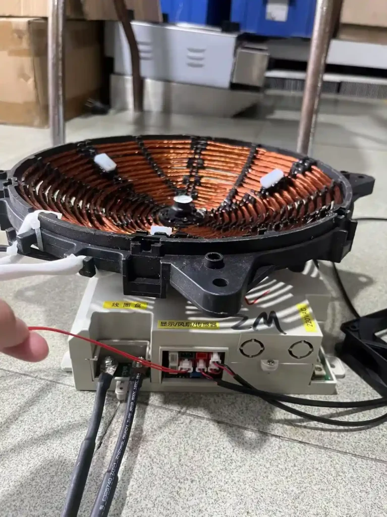
One pattern jumps out: the materials that set the performance ceiling sit in the coil and main board stages. Copper quality drives thermal efficiency. IGBT grade drives power stability.I’ve also included a disassembly diagram showing all the raw materials combined together. Feel free to take a look if you’re interested.
That’s also why buyers conducting an induction cooker factory audit spend the most time in those two workshops. The critical stuff is visible. You can tell quickly if it’s up to par.
How Each Production Stage Is Executed in Detail
Electrical Core Components — How They’re Made
1. Coil Disc Winding — Tension and Turn Count, Precisely Locked
This step decides whether the cooker converts electricity to heat efficiently. The winding line uses automatic equipment with electronic tensioners. The principle: electromagnetic damping. No friction pads involved — a magnetic field locks the pull force. So no matter how the line speed changes, the wire tension stays constant.
Turn count is handled by a built-in counter. Commercial high-power coils typically need 20 to 32 turns. One extra or one fewer — the inductance drifts and heating efficiency drops. A counter-tension mechanism keeps the wire tight. No overlap, no jumping. That’s what makes a conforming coil.
Does this control actually hold up? A Southeast Asian chain restaurant buyer tested it. During his factory visit, he pulled five coil discs at random — different batches — and sent them to a third-party lab for inductance measurement. Every single one came back within ±1.5% of the nominal value. In his audit report he wrote: “This was one of the key reasons I decided to place long-term orders.”
2. Main Board SMT and Reflow Soldering — Four Temperature Zones, Synchronized
The main board is the brain. Hundreds of components sit on it. One bad solder joint kills the whole board. High-speed pick-and-place machines put resistors, capacitors, and driver ICs onto solder-paste-printed PCBs at very tight tolerances.
After placement, the board enters the reflow oven — four zones in sequence. Preheat zone: temperature rises at 1–3°C per second, reaching about 150°C. Soak zone: holds at 140–200°C for 60–120 seconds so flux activates and all parts heat evenly.
Reflow peak zone: temperature hits 230–260°C for 20–40 seconds. Solder paste melts and joints form. Cooling zone: drops at 2–4°C per second. Joints solidify. If any zone goes wrong, you get weak solder joints.
Every morning, the first board off the line gets its temperature profile measured by thermocouple and archived. This rule exists because of a specific incident: in 2021, a batch of boards came out with widespread cold joints. Root cause? The oven temperature had drifted that day and nobody caught it fast enough. After that, this check became mandatory — no measurement, no production start. Since then, first-pass yield has stayed above 99.2%. The same problem has never come back.
3. IGBT Module Assembly — Thermal Interface and Torque Done Right
The IGBT generates the most heat in the entire cooker. Poor heat dissipation means throttling at best — burned modules at worst. The IGBT module assembly procedure has three steps. First: screen-print a uniform layer of thermal grease onto the heat sink surface. Second: align and place the IGBT module. Third: tighten screws with a torque wrench in a diagonal pattern, going only one-third of the target torque at a time, repeating over several rounds until fully seated.
How do you confirm it’s done right? Look at the edges. You should see a thin, even bead of thermal grease squeezed out around all four sides. That means no air gaps at the interface — thermal resistance is minimized.
This seems like a small detail. It’s actually the biggest manufacturing gap between commercial and household units. A household cooker runs at low power for short bursts — imperfect contact is survivable. A commercial unit above 5000W running all day? Even a tiny increase in interface thermal resistance compounds over hours into a real failure risk.
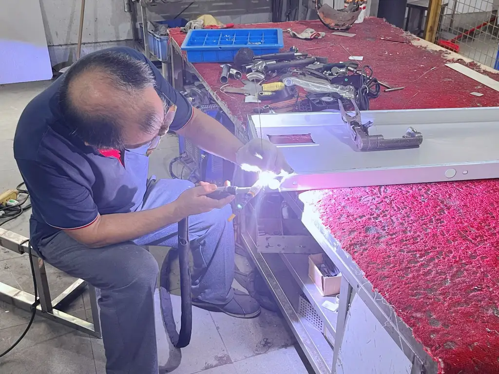
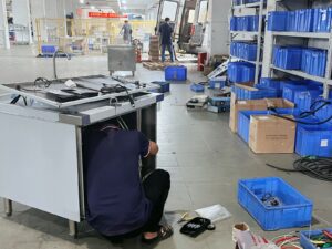
Full Assembly and Factory Testing — How It’s Done
All core parts ready. They hit the final assembly line. The order is fixed and can’t be shuffled:
Coil disc goes in first, screw-locked to the enclosure. Control board gets mounted into the assembly box. Cooling fan goes in — airflow must point directly at the IGBT heat sink. Last, the NTC temperature probe plugs into the hole at the coil disc center. Four parts, four steps, that exact sequence. Why fixed? Because each later part blocks wiring access for the one before it.
Then comes internal wiring. Power cable, signal lines, fan supply — all pressed into terminals following the wiring diagram. After connection, every single line gets a continuity check. No missed connections, no misroutes. Only then does the cover go on. A commercial cooker has a dozen-plus wire harnesses inside. One wrong connection could mean a short or a dead function. There’s no “close enough” here.
Assembled units go straight into burn-in. No sitting in a warehouse. No waiting. Each unit connects to a dedicated test bench — independent station system — and runs at rated power, full load, continuously for at least 4 hours.
A hot pot chain’s engineer once showed up for a supplier evaluation carrying his own power analyzer. He monitored an entire burn-in cycle on-site, then compared his readings point-by-point against the factory’s backend data. Deviation: under 0.3%. His words: “Your test benches aren’t just for show.”
Burn-in isn’t the last step either. After that: insulation withstand voltage test, leakage current check, power accuracy across all settings, and final cosmetic inspection. Pass everything — then and only then — the unit gets a conformity label and goes into packaging.
Here’s what gets monitored during burn-in and what counts as a pass:
| What’s Monitored | Test Conditions | Pass Criteria |
|---|---|---|
| Input Power | Rated voltage, sustained full load | Within ±5% of rated power |
| Operating Current | Rated power, continuous | Must not exceed max design current |
| IGBT Module Temp | Full power, entire run | Must stay below design limit (typically ≤85°C) |
| Coil Disc Temp | Full power, entire run | Must stay within insulation class rating |
| Fan Speed | Real-time, entire run | Stable, within ±10% of rated RPM |
| Duration | Uninterrupted full load | Minimum 4 hours, no anomalies |
Why This Production Process Is Designed This Way
Commercial induction cookers live in a different world from household ones. High heat. Grease. Humidity. Running 12+ hours a day without a break. Every component sits near its limit the entire time. Use a household-grade production mindset here, and failures become a countdown — not an “if.”
This process wasn’t designed in a vacuum. It was shaped by commercial kitchens. When a cooker dies at lunch rush, it doesn’t just stall one dish — it jams the entire line. Repair cost is nothing compared to the revenue lost. So every sequence and checkpoint exists for one purpose: once it reaches the customer, it must not go down.
Failure Costs in Commercial Settings Force Standards to Move Earlier
A household cooker fails? Worst case: a refund and a bad review. Commercial? One dead unit cripples half the kitchen. Turnover drops. Complaints pile up. Worst case: food safety trouble. You cannot afford to catch problems only at the last gate.
So commercial induction cooker quality control here shifted from “catch it at the end” to “catch it where it happens.” Every stage has its own checkpoint.
Inspection checkpoints sit inside each stage — not after final assembly. The PCB gets tested after SMT. Tested again after IGBT soldering. The full unit runs through burn-in. Layer by layer, not one big pass-fail at the finish. Why? Because once power modules are built into the complete unit, pulling them back out to investigate wastes time and damages surrounding parts.
In 2019, an internal test proved it. Same batch of boards. One group: tested only after full assembly. Other group: tested at three intermediate points. Result? The first group’s final defect rate was 2.3× higher. On top of that, rework on those boards destroyed 11% of adjacent components. The numbers made the argument.
Incoming materials get 100% inspection on critical parts — not sampling. This rule came from a real incident. A Southeast Asian chain client had 3 units blow capacitors after 8 months. Same batch. Investigation traced it back: the capacitor supplier had quietly changed electrolyte formulas without telling anyone. After that, dielectric constant spot-checks and accelerated aging tests were added at the receiving dock. Bad materials don’t get past the door anymore.
More inspection steps actually save buyers money. Yes, more process means a slightly higher unit cost. But a long-term Middle Eastern distributor put it bluntly during his audit: “I’ll gladly pay a few percent more per unit over handling one field repair. Sending a technician to a restaurant site costs more than the cooker itself.” That’s not factory marketing. That’s a buyer who did the math. Commercial customers aren’t buying the cheapest unit price — they’re buying the lowest total cost over the product’s life.
High-Power Components Don’t Tolerate “Test It All at the End”
Power levels range from 3.5kW to 35kW. That’s a completely different world from household. At these levels, IGBTs, resonant capacitors, and coil discs all run under high current and high temperature — right near material limits. A cold solder joint, a slightly thin wire, a partly blocked cooling path — invisible during a quick check, guaranteed to fail after hours at full load.
So the rule is: test each module on its own first, then put it all together. No assembling everything at once and crossing fingers when power goes on.
This comes from hard data. In 2021, the engineering team sorted all historical field failures by root cause. Result: 72% traced back to a single module’s parameter drifting out of spec. Catching that drift at the module stage costs one-fifth of what finding it in the assembled unit costs. The data came in, the process changed immediately. “Module-level verification before integration” became the standard.
Here’s what the two approaches look like side by side — numbers from actual production records and field feedback:
| Dimension | Step-by-Step Verification | Traditional All-at-Once Assembly |
|---|---|---|
| When IGBT solder defects get caught | Right after module soldering | Only after full unit powers on |
| Average time to find a fault | 8 minutes (variables already narrowed) | 45+ minutes (everything tangled together) |
| Collateral damage from rework | <1% | ~12–15% |
| First-pass rate at burn-in | 97.6% | ~88–91% |
| Customer first-year failure rate | 0.8% | Industry average ~3–5% |
Seven stages covered. One takeaway: manufacturing quality in a commercial induction cooker isn’t guaranteed by final inspection. It’s built up through control at every single station. Choosing a commercial induction cooker supplier works the same way — don’t just read the spec sheet. Ask whether they actually manage each stage.
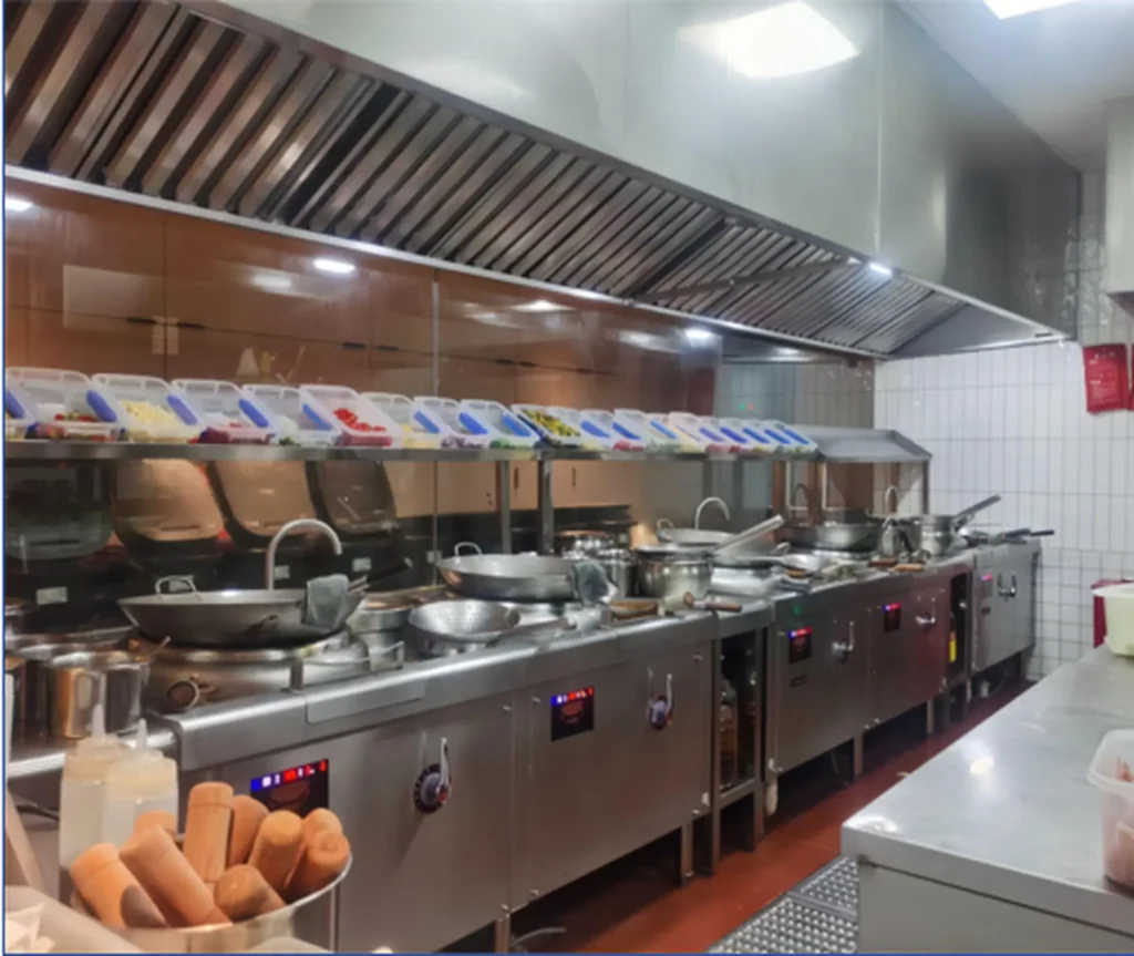
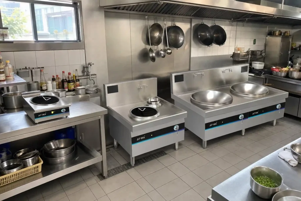
If you want to see what comes off a production line built this way, ATRX — as a manufacturer that controls all seven stages in-house — puts its full commercial cooktop range on display for direct evaluation.
The full commercial induction cooker manufacturing process is here for you to reference. Use it as a yardstick, not a brochure. If you’re comparing factories right now, bring your engineers and walk the line in person. Seeing beats guessing.
Ready to take supplier screening further? Read next: How to Choose a Reliable Commercial Induction Cooker Manufacturer — three verifiable criteria that help you cut “looks professional, can’t deliver” factories in round one.
Common Questions People Ask
Q: Do different power levels mean a fundamentally different production process?
Same seven stages. Different parameters. A 3.5kW model uses Litz wire with fewer strands and about 20 turns. A 15kW+ model needs thicker wire bundles, more turns, and an upgraded cooling structure — dual fans or even liquid-assisted cooling.
IGBT current ratings, heat sink area, and thermal grease thickness all scale with power. On the production line, each model has its own parameter set. There’s no “one config fits all.”
Q: If I do OEM (private label), does the production process get simplified?
No. OEM orders run on the same line, same inspection standards as in-house branded units. Nobody skips a test just because a different logo goes on the front. The only differences are cosmetic — panel printing, labels, packaging design — all customized per client.
Coil winding specs, SMT parameters, IGBT assembly torque, burn-in duration — all identical. During any induction cooker factory audit, you’ll see OEM and proprietary-brand products on the same burn-in racks, side by side. No separate treatment.
About the author
ATRX Team| 18 Years Commercial
Induction Cooker Manufacturer in China
Induction Cooker Manufacturer in China
Related Posts
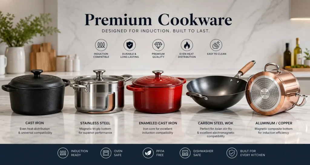
What Cookware Works on Induction? Compatibility Guide & Best Materials Explained
07/28/2026

Best Commercial Induction Cooktop for Restaurant: Types, Specs & Buying Guide (2026)
07/26/2026
How to Open a Hot Pot Restaurant in a Mall: Fire Code, Equipment & No Open Flame Solutions
07/24/2026
Gas vs Induction Cooktop: Energy Efficiency, Running Costs & Real Performance Compared
07/21/2026
Commercial vs Home Induction Cooktop: What’s the Difference
07/18/2026
Induction vs Ceramic Cooktop: Key Differences in Heating, Efficiency & Safety
07/15/2026
High-End Commercial Induction Cooker: What Makes It Premium and How to Choose the Right One
07/12/2026
Industrial Induction Wok Burners (15 kW–30 kW): How They Differ from Standard Commercial Models
07/07/2026
Commercial Induction Wok Burners: Countertop vs. Built-In vs. Freestanding — Which Fits Your Kitchen layout?
07/06/2026
Commercial Induction Wok Range: What to Cook at Every Power Level (3.5 kW–30 kW)
07/05/2026