What Manufacturing Standards Do Induction Coils Need for 8+ Hours of Daily Use
05/31/2026
Estimated reading time: 2 minutes
IN THIS ARTICLE
What Material and Build Standards Do Continuous-Use Coils Require?
Copper Grade and Wall Thickness Rules for 8-Hour Coils
1. Copper grade must be C12200 oxygen-free copper, certified under ASTM B280.
A commercial induction cooker coil running 8+ hours a day needs the right copper. Get this wrong and nothing else matters. The industry standard is C12200 phosphorus-deoxidized copper under ASTM B280. Copper purity sits above 99.9%. Conductivity stays stable. Weldability is excellent.
Why this exact grade? Even trace impurities create localized high-resistance spots under heavy current. Heat piles up at those points. Coil lifespan tanks.
We learned this at ATRX the hard way. Early on, one batch of copper tubing came in slightly below purity spec. Within two weeks, customers reported surface discoloration and dropping efficiency. We pulled the coils apart. Microscopic hot spots everywhere — all from impurities. After that, the rule became permanent: every incoming batch gets its quality certificate checked. Alloy grade and purity don’t match C12200/ASTM B280? Shipped back. No discussion.
2. Wall thickness isn’t “thicker = better.” The number that matters is the t/δ ratio.
Lots of people assume thicker copper tubing lasts longer. It doesn’t work that way. What actually determines long-term stability is the ratio of wall thickness (t) to electromagnetic reference depth (δ). Fluxtrol ran detailed FEA simulations on this. The findings are clear.
When t/δ drops below 1, current heats the tube wall volumetrically. Losses spike. A few hours in, copper temperature can blow past 250°C. At that point, cooling water starts vaporizing. The coil is on borrowed time.
Between 1 and 1.2? That’s the sweet spot. Peak efficiency, manageable heat. Above 1.2, efficiency barely improves — but the longer heat path actually makes cooling harder. So the window is narrow. Below 1 fails. Too far above 1.2 doesn’t help.
3. Different frequencies need different wall thicknesses. Check by frequency at acceptance.
At 3 kHz, reference depth is large. Recommended wall thickness: 0.062 inches (about 1.57 mm). At 10 kHz, reference depth shrinks. 0.048 inches works. The process is simple: receive the coil, check the copper certificate, measure the wall, calculate t/δ at your actual operating frequency. Below 1? Reject it. End of story.
Last year a Southeast Asian customer asked during a factory visit — does a fraction of a millimeter really matter that much? We showed him thermal imaging from two coil sets side by side. The group with t/δ below 1 was running nearly 40°C hotter by hour four. He didn’t need more explanation after that.
Insulation and Structure Specs That Handle Daily Thermal Cycling
Eight hours a day means the copper surges hot at startup, then cooling water yanks it back down at shutdown. That’s hundreds of expand-and-contract cycles every single day. Insulation spacers, adhesive layers, inter-turn structures — if any of these can’t handle the cyclic stress, the coil falls apart from the inside. Here’s what must pass inspection before anything ships.
Inter-turn insulation spacers need at least IEC 60085 Class F rating (155°C). Class H (180°C) is better. Common materials: synthetic laminates and FRP fiberglass spacers. Drop below Class F and you get aging, cracking, carbonization. Then inter-turn short circuits. Then the coil burns.
This isn’t theory. We tested it. Same coil design, two groups — one with Class B spacers (130°C), one with Class H (180°C). We simulated 8-hour daily use for 30 days. Class B already had visible micro-cracks at the edges. Class H looked brand new. We switched the entire production line to Class H that same month.
Adhesive layers matter just as much. The epoxy bonding flux concentrators to copper tubing needs thermal conductivity of at least 1 W/m·K. Lower than that and the adhesive becomes a heat trap. Thermal energy gets stuck in the copper tube corners — exactly where the coil runs hottest. Fluxtrol’s simulations confirmed this is the peak temperature zone.
Inter-turn spacing can’t be ignored either. Uneven gaps mean asymmetric magnetic fields. Current density spikes in certain spots. Those spots fatigue first. A fraction of a millimeter off today becomes a crack origin six months from now.
| Inspection Item | Manufacturing Standard Requirement | What Happens If Non-Compliant |
|---|---|---|
| Inter-turn insulation spacer thermal rating | IEC 60085 Class F (155°C) to Class H (180°C) | Aging and cracking → inter-turn short circuit → coil burnout |
| Adhesive layer thermal conductivity | ≥ 1 W/m·K (epoxy resin base) | Creates thermal resistance → localized overheating → thermal fatigue cracking |
| Inter-turn spacing tolerance | Within ±5% of design value | Asymmetric magnetic field → localized overload → premature failure |
| Insulation material type | Synthetic laminates / FRP fiberglass spacers | Ordinary materials can’t survive hundreds of daily thermal cycles |
| Shipping inspection documents | Thermal rating certificate + thermal conductivity report + spacing records | Missing items make quality untraceable; don’t accept the delivery |
Spacing uniformity comes down to process control during winding. Was tension kept constant? Was pitch locked? Were bend radii constrained by tooling? All of that gets decided at the winding stage. For a deeper look at how winding procedures shape final product consistency, see this guide: How Commercial Induction Cooker Coils Are Wound.
What Cooling Standards Keep Induction Coils Safe in All-Day Operation?
Home induction cookers get switched off after use. The coil has plenty of time to cool on its own. Commercial kitchens don’t work that way. Eight hours straight means heat stacks up without a break. The cooling system falls behind even slightly and temperatures run away. Meeting proper induction coil cooling requirements isn’t optional for all-day operation — it’s what keeps the coil alive.
Water Pressure and Flow Rates That Prevent Overheating in Long Shifts
Buyers ask about power. They ask about materials. Almost nobody asks what cooling water pressure the coil actually needs. Last year a Southeast Asian customer came to ATRX for a factory audit. He brought burned-out coil samples with him. The copper tubing inside was blue-black — classic film boiling burnthrough. Turns out his old supplier calculated water pressure for intermittent use. It was never designed for all-day continuous duty.
When copper tube inner wall temperature hits 250°C, cooling fails instantly. Here’s why: a steam film forms inside the water channel. Steam conducts heat tens of times worse than liquid water. The cooling path is essentially blocked. What comes next happens in seconds — the copper burns through. This isn’t a worst-case scenario. Under 8+ hours of continuous operation with poor cooling design, you will hit this threshold.
Continuous operation needs at least 40 psi cooling water pressure. This number comes from FEA simulation, not guesswork. Going from 20 psi to 40 psi drops thin-wall coil temperature (0.048 inch) by 40°C. Thick-wall coils (0.125 inch) only drop 15°C. Two takeaways: water pressure works, and pressure specs must match wall thickness. One without the other isn’t enough.
When you ask suppliers for cooling specs, add one question: “How many hours of continuous runtime was this calculated for?” We hit this problem over and over on WhatsApp with customers. The supplier’s recommended pressure was based on a 30-minute test. Apply those numbers to all-day use and the cooling margin disappears. Simple filter: demand the “continuous runtime assumption” in writing. If they can’t state it, question the whole parameter set.
Water Channel Design Standards That Hold Up Over 8+ Hours
Water channel design differences don’t show up during intermittent use. Run the coil 8+ hours straight and they become obvious fast. We tested this internally. Same batch of coils, two groups. One ran intermittent mode for two weeks — totally fine. The other switched to continuous 8-hour mode. Day five: localized overheating.
We opened it up. The problem was one bend. Curvature radius too tight. Cooling water slowed to a crawl at that spot, creating a dead zone. Heat stacked up with nowhere to go.
With intermittent duty, that defect is harmless — the coil cools between runs. Continuous duty has no buffer. Heat flows in but never fully flows out. The hot spot gets worse each day. Scale builds faster. It snowballs.
So for continuous operation, water channel inner wall smoothness, consistent bore diameter, and adequate bend radii all become hard requirements. When buying, ask for water channel cross-section drawings and flow resistance test reports. Supplier can’t provide them? That tells you they don’t do systematic water channel quality control.
| Parameter | Intermittent Use Standard | Continuous 8+ Hour Standard |
|---|---|---|
| Water channel cross-section | Round or square acceptable | 5/8-inch square recommended (more heat dissipation contact area) |
| Bend curvature radius | No strict limits | ≥1.5× tube diameter to avoid turbulence dead zones |
| Inner wall smoothness | Standard machining acceptable | Precision machining required to reduce scale adhesion points |
| Bore consistency | ±10% deviation allowed | Within ±5%, uniform flow velocity throughout |
| Documentation required from supplier | Basic spec sheet | Cross-section drawings + flow resistance test data |
What Certifications Prove an Induction Coil Can Handle 8+ Hours Daily?
Commercial kitchen induction cookers run 8 hours minimum. Lunch rush straight into dinner rush is normal. Whether a coil survives that isn’t up to the supplier’s word. What actually backs you up is the certification system and the test data behind it. Certifications prove the manufacturing process is controlled. Test data proves the finished coil can take real-world punishment. A supplier that can’t show both? Skip them, regardless of price.
Understanding induction coil continuous duty standards — and which certifications verify them — is the fastest way to separate real suppliers from the rest.
ISO and IEC Certifications That Cover Heavy-Duty Coil Manufacturing
For continuous-operation induction coils, suppliers need to show at least these three:
ISO 9001 Quality Management System. This is the floor. It means copper tubing inspection, coil winding, and final testing all have documented records, sign-offs, and traceable steps. Without it, production runs on gut feel. Maybe that’s fine for light use. For 8 hours a day, process drift catches up eventually.
IEC 62076 induction coil certification. This is the IEC’s dedicated standard for testing industrial induction furnace equipment. It defines what to test, which metrics matter, and under what conditions. A supplier validated against this framework has at least proven their coil’s power handling and thermal stability through systematic evaluation — not just a two-minute smoke test before stamping “approved.”
IEC 63078 (induction through-heating performance verification). This goes deeper than IEC 62076 into sustained heating specifically. Its test items map directly to temperature rise control and efficiency loss under prolonged high-power output. For coils facing 8+ hour daily shifts, this standard’s scope fits actual working conditions most closely.
When ATRX screened new coil suppliers last year, we made all three mandatory at the inquiry stage. Nearly 40% of candidates got cut right there. Some had ISO 9001 but zero IEC testing. Others had certificates that expired six months ago — still posted on their website.
We shared this screening approach with customers during factory visits. A lot of procurement managers said the same thing: they’d always picked suppliers on price and lead time, never checked IEC certs. No wonder coils started dying at six months. The logic is simple. Certifications are checks a third party already ran for you. They save you the cost of finding problems yourself.
Thermal Fatigue Test Data to Request Before Placing Orders
Certifications tell you the factory’s process is sound. But can the specific coil you’re buying actually survive continuous operation? That takes induction coil thermal fatigue testing data.
Here’s how thermal fatigue works. Power on — copper heats up, expands. Power drops — cooling water pulls temperature down, copper contracts. That’s one cycle. A commercial induction cooker goes through 15 to 20 power switches per hour. Over 8 hours, that’s 120 to 160 cycles. Over a year, close to 50,000. Each cycle “pries” the copper surface micro-cracks a little wider.
Once cracks grow far enough: water leaks, short circuits, machine burnout. One cooker goes down and the whole kitchen’s output rhythm breaks.
So before ordering, demand thermal fatigue data. Don’t accept “we tested it, it’s fine.” Here’s what to ask for and how to judge it:
| Data Item to Request | What to Look For |
|---|---|
| Thermal cycling test parameters | Power density, on/off timing, cooling water temp and flow — must match your real conditions, not ideal lab settings |
| Total cycle count | At 8h/day, 18 switches/hour, 3-year target life = ~19,700 cycles/year minimum. A test that stopped at 2,000 cycles proves almost nothing |
| Post-cycling metallographic inspection | Any crack initiation on copper surfaces or brazed joints? Need cross-section lab reports, not “looks fine visually” |
| Peak temperature throughout testing | Copper inner wall max must stay under 250°C. Above that, steam film forms, heat transfer collapses, copper burns through |
| FEA simulation report | Temperature and stress distribution for both steady-state and transient cycling. Stress must stay below copper fatigue limits within design life |
We didn’t make this list from scratch. One candidate supplier spent two weeks sending messages back and forth with us. Their initial proof? A 30-minute temperature rise report. Power on for half an hour, one temperature reading, stamped “qualified.” We pushed back item by item using the table above. They finally admitted they’d never run tests past 2,000 cycles.
What’s 2,000 cycles in practice? About two weeks of commercial use. Meaning after three months, this coil enters completely unverified territory. Lots of commercial induction cookers start breaking down at the six-month mark. This is often why.
Bottom line: no complete thermal fatigue data and FEA report means no proof it works for continuous duty. However good the price looks, you’re gambling.
Common Questions People Ask
Q1: Supplier pricing varies wildly. Can cheap coils handle 8-hour duty if we just increase cooling?
No. Cooling only fixes the heat removal side. Insufficient copper purity, wrong wall thickness ratio, low insulation rating — these are built-in defects. More water pressure won’t undo them. Budget coils typically cut costs at the material and process level. Under continuous heavy load, those shortcuts show up as hot spots, efficiency drop, and inter-turn shorts. Check every material and structural standard in this article first. Confirm compliance, then compare prices. Not the other way around.
Q2: Our coils are already installed and the supplier never provided fatigue data. Any way to check remaining life on-site?
Three things to watch. First: heating slows at the same power setting. That means coil resistance has climbed — micro-cracks expanding. Second: cooling water outlet temp is 5°C+ higher than at install, with no change in flow rate. Likely scale or narrowing inside the tube. Third: surface discoloration or yellowed insulation. Any one of these appears, schedule a shutdown inspection immediately. Don’t wait for a leak or a burnout.
Q3: Supplier says “CE certified” covers everything. Do I still need IEC 62076 and IEC 63078?
CE is a European market access mark. It covers electrical safety and electromagnetic compatibility — the basics. It does not test whether an induction coil survives continuous high-power use without overheating. Put simply: CE proves it won’t electrocute anyone. It doesn’t prove it won’t burn out after 8 hours a day. IEC 62076 and IEC 63078 specifically evaluate induction heating performance under sustained operation. Both are necessary. A supplier relying on CE alone almost certainly hasn’t done long-duration thermal validation.
Every standard in this article — copper grade, wall thickness ratio, insulation class, cooling channel design, IEC certification, thermal fatigue data — is built into the coils inside ATRX cooktops. If you’re sourcing units that are engineered for continuous commercial kitchen duty from day one, browse our full range as a commercial induction cooktop manufacturer.
About the author
ATRX Team| 18 Years Commercial
Induction Cooker Manufacturer in China
Induction Cooker Manufacturer in China
Related Posts
What Cookware Works on Induction? Compatibility Guide & Best Materials Explained
07/28/2026
Best Commercial Induction Cooktop for Restaurant: Types, Specs & Buying Guide (2026)
07/26/2026
How to Open a Hot Pot Restaurant in a Mall: Fire Code, Equipment & No Open Flame Solutions
07/24/2026
Gas vs Induction Cooktop: Energy Efficiency, Running Costs & Real Performance Compared
07/21/2026
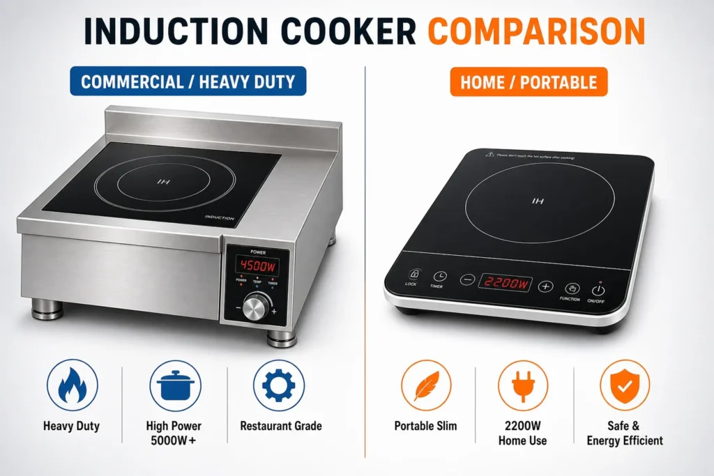
Commercial vs Home Induction Cooktop: What’s the Difference
07/18/2026
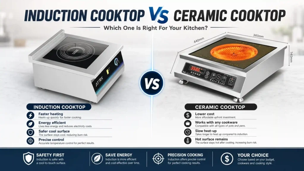
Induction vs Ceramic Cooktop: Key Differences in Heating, Efficiency & Safety
07/15/2026
High-End Commercial Induction Cooker: What Makes It Premium and How to Choose the Right One
07/12/2026
Industrial Induction Wok Burners (15 kW–30 kW): How They Differ from Standard Commercial Models
07/07/2026
Commercial Induction Wok Burners: Countertop vs. Built-In vs. Freestanding — Which Fits Your Kitchen layout?
07/06/2026
Commercial Induction Wok Range: What to Cook at Every Power Level (3.5 kW–30 kW)
07/05/2026