How Commercial Induction Cooker Coils Are Wound – Wire, Structure & Production Process
05/30/2026
Estimated reading time: 2 minutes
What Wire and Structure Are Used to Wind Commercial Induction Cooker Coils?
A commercial induction cooker coil either works well or it doesn’t. It comes down to two things: what wire goes in, and how that wire sits on the disk.
Wire first. The industry standard for any Litz wire induction cooker is multi-strand twisted copper. Dozens of thin copper strands are braided together. Why bother? Because at high frequencies, current doesn’t travel through the center of a conductor. It only rides the surface — that’s the skin effect. One thick wire means most of the cross-section is wasted. Litz wire fixes this by giving current many small paths instead of one big one. Less wasted copper, lower losses.
Structure next. Commercial units all use a flat spiral coil winding process. But it’s not a uniform spiral from center to edge. It’s two zones — tight turns in the middle, spaced-out turns toward the rim. The magnetic field needs to be shaped a certain way, and this two-zone layout does the job. More on that below.
Litz Wire Specs Matched to Different Power Levels
The selection rule is simple. Higher power means more current. More current needs more copper cross-section. You get there by making each strand thicker, adding more strands, or both.
But you can’t just pile on material. If each strand gets too thick, the skin effect comes back. If you add too many strands, the bundle goes stiff, winding gets harder, and cost climbs. Every power level has a sweet spot.
At our ATRX factory, we didn’t find these sweet spots in a textbook. We tested them on the production line, batch after batch. Here’s one that stuck with us: a Southeast Asian client messaged on WhatsApp about wire for a 1200W model. He wanted to copy the 0.20mm × 80-strand spec from a household unit.
Our engineer sent him internal test data. Switching to a 15-strand twisted configuration dropped coil temperature rise by 8°C. More strands isn’t automatically better. What matters is the right combination of strand diameter and strand count at your specific operating frequency.
This table shows configurations we’ve validated on our production line over many runs. Use it as a quick reference:
| Power Level | Litz Wire Specification | Application Notes |
|---|---|---|
| 800W | 0.35mm × 28 strands | Thick strands, fewer of them, low cost — handles small commercial countertop units fine |
| 1200W–1500W | 15-strand twisted / 18-turn twisted | Mid-power workhorse — balances current capacity and high-frequency performance |
| 2000W | 0.28mm × 60 strands | Thinner strands, doubled count, big total cross-section, very low AC resistance |
| Above 2000W | Custom per project | Needs individual calculation based on drive frequency (20kHz–40kHz) and cooling design |
Wire spec is one half of the equation. The other half is whether that coil can hold up hour after hour at full load — the reality of a commercial kitchen. If you need to understand how coil temperature rise, insulation class, and duty cycle ratings work together under continuous operation, read our breakdown on induction coil continuous duty standards.
If you’re sourcing finished cooktop units built around these wire specs, browse our catalog as a commercial induction cooktop manufacturer — 3.5KW to 8KW models with OEM branding available.
Dense and Sparse Sections in Flat Spiral Winding
Open up any commercial induction cooker coil disk. You’ll see it immediately: inner turns packed tight, outer turns clearly spaced apart. That’s not sloppy work. It’s deliberate.
Here’s why. Dense turns in the center concentrate the magnetic field. The pot bottom center heats up fast — that’s your main fire zone. Sparse turns toward the rim spread the field outward. The pot edge gets heat too — no more cold ring. Dense plus sparse together gives you even heating across the whole pan.
How is the split actually done? We disassembled multiple production batches and measured. Here’s what a typical 210mm disk looks like:
Inner dense section: about 13 turns. They sit nearly touching, zero gap, spreading outward from the center hole. This zone covers most of the disk’s radius. Roughly 60% of total magnetic flux comes from here — the high-heat core under the pot center.
Outer sparse section: about 10 turns. Evenly spaced, running all the way to the disk edge. Job: push the heating zone outward so the rim isn’t a cold spot.
The transition between dense and sparse falls at about 55%–60% of the disk radius. That’s the dividing line between “concentrated core heat” and “edge coverage.” Change the pot size, and this transition point has to move with it. Bigger disk means more sparse turns.
Last year a group of Malaysian clients visited our factory. We set up two disks side by side: a 210mm standard and a 340mm large. The large one had noticeably more sparse turns in the outer zone. They pulled out a thermal camera on the spot. The temperature maps told the whole story — shift the dense-to-sparse ratio, and uniformity shifts with it. Beat any slide deck.
How Are Commercial Induction Cooker Coils Wound on the Production Line?
Heating performance lives or dies with the coil disk. Good winding means stable magnetic field. Bad winding means the whole machine underperforms. Volume production doesn’t rely on hand-winding anymore. It’s all automated. Here’s how commercial induction cooker coil winding actually works — equipment first, then process.
Winding Machine Types and Key Equipment Specs
On the factory floor, coils are wound by a dedicated induction coil winding machine. We went through several selection rounds before locking in what our ATRX workshop runs today. Here’s what it does:
Servo motor spindle, 0–5,000 rpm, steplessly adjustable. Center dense winding needs slow, precise rotation. Outer sparse winding can go faster to hit cycle time. Servo drive makes speed changes smooth — no jerks. Copper wire hates sudden changes. One jerk creates stress concentration in the wire.
Wire diameter range: 0.3mm–5.0mm. That covers all the Litz wire and single-strand enameled wire used in commercial induction cookers. Switching diameter doesn’t mean swapping out the spindle or fixtures. Adjust the guide nozzle and tension settings — takes a few minutes.
Cycle time: about 25 seconds per piece. One machine puts out 140+ coil disks per hour, steady. Last year some Southeast Asian clients visited and were surprised by this. Their previous suppliers ran 40+ seconds per piece.
PLC-controlled winding path. Turn count, spacing for each zone, start and stop positions — all in the program. The wire guide rail moves with the spindle, precision within ±0.1mm. No one needs to watch it. The program keeps every batch identical.
Closed-loop tension control. A magnetic powder brake or servo tensioner adjusts wire tension in real time. Too loose and the wire buckles up. Too tight and it gets stretched thin. We ran internal tests: keep tension fluctuation within ±3%, and finished inductance deviation stays under 1%. That’s the difference between tight control and guesswork.
Bottom line: servo spindle handles speed, PLC handles path, tensioner handles wire state. Three systems, each doing their job. That’s how identical coils come out one after another.
The Winding Process From Empty Disk to Finished Coil
Equipment covered. Now the actual steps. One coil disk goes from empty frame to finished in five moves. This is what overseas clients ask about most when we talk tech on WhatsApp. It’s not complicated — but control details at each step make or break the result.
Step 1: Mount and Clamp the Coil Frame
Empty bobbin goes into the rotating fixture. Pneumatic clamp locks it down. Fixture accuracy sets the concentricity for everything after it. So the machine runs a zero-position check every time. If it’s off — alarm, full stop.
Step 2: Thread Wire and Clamp the Lead
Copper wire comes off the spool, passes through the tensioner, over guide wheels, through the wire guide nozzle, and reaches the starting slot on the disk. The clamping mechanism locks the wire lead. Why lock it hard? Because the moment the spindle spins, a slipped lead means the whole disk is scrap.
Step 3: Dense Wind First, Then Sparse Wind Per Program
Spindle turns. Wire guide moves outward from center. The center section is dense — turn pressed against turn, no gaps. Magnetic flux concentrates here. This is where heating is strongest.
When the guide reaches the outer zone, it switches to sparse winding. Gaps appear between turns. The magnetic field fans outward to cover the pot edge and prevent overheating at center. The switch point is written into the PLC program, accurate to 0.1mm.
Step 4: Side Pressing to Ensure Precision
The whole time the coil winds, a cylinder-driven pressure roller presses against the copper wire from the side. Constant radial force. Without it, the coil bulges or drifts out of alignment.
We found this out the hard way. When press force was set too low internally, finished coils had localized air gaps once installed. Heating went uneven. Bumped up the pressure parameter — problem gone.
Step 5: Cut Wire and Secure Terminals
Last turn in place. Spindle stops. Pneumatic scissors cut. Wire lead goes into a terminal clamp — spot-welded or soldered to the connection terminal. Electrical connection done. One finished coil disk, ready for the next inspection step.
Here’s all five steps in one table:
| Step | Key Action | Control Point | Impact on Finished Product |
|---|---|---|---|
| Mount & Clamp Frame | Bobbin in fixture, pneumatic lock | Zero-position check, alarm on deviation | Sets coil concentricity |
| Thread & Clamp Lead | Wire through tension system, lead locked | Clamping force must hit spec | Prevents start-point slip |
| Dense Then Sparse Wind | Center tight, outer section gapped | PLC pitch switching ±0.1mm | Determines magnetic field and heating uniformity |
| Side Pressing | Roller applies constant radial force | Cylinder pressure stays constant | Ensures flatness, kills air gaps |
| Cut & Secure Terminals | Wire cut, terminal soldered | Joint strength and contact resistance | Long-term reliability and electrical safety |
Five steps, 25 seconds. Looks simple. But parameters off by a hair and the coil falls short. Batch consistency and long-term reliability hide inside these details.
What Winding Techniques Keep Commercial Induction Cooker Coils Consistent?
In commercial induction cooker coil winding, every turn’s position, tightness, and alignment directly shapes the magnetic field. Mass-produce hundreds or thousands of coils — they all need to hit the same electrical specs. Human feel can’t do that. Machines can.
We’ve been at this long enough to know where things go wrong. In the induction cooker coil manufacturing process, consistency comes down to two things: keeping wire tight and straight while it winds, and handling speed transitions without error. Here’s how each works.
Tension Control and Side Pressing During Winding
Tension control and side pressing — these two keep every turn tight and aligned. Last year a Turkish client visited our factory. He stood at the winding station for almost 30 minutes. One question, over and over: “How do you make sure every coil comes out the same tightness, the same alignment?” Here’s what we showed him:
Servo motor delivers constant tension. A DC servo-driven active tensioner with built-in torque sensor. It measures and adjusts in real time. Speed changes — startup, acceleration, deceleration, stop — the tensioner responds in 0.2 seconds. Pull too hard, the wire thins and resistance drifts. Pull too soft, the wire slacks and gaps open between turns. Constant tension blocks both problems.
What that gives you: every turn goes on at the same tightness. DC resistance barely fluctuates across a batch. Our QC numbers: with servo tension running steady, same-batch resistance stays within ±1.5%.
Side press plates shape the coil as it winds. These coils are flat spirals — wire laid turn by turn from center outward. Any sideways drift and turn spacing goes uneven. The fix: press plates mounted on the winding machine push from the outside continuously. Each fresh turn gets squeezed into position right against the last one. Winding and shaping happen at the same time.
You need both — tension for tightness, side pressure for alignment. They run together. One Southeast Asian client posted comparison photos in a tech group: his old supplier skipped the side-pressing step. Coils looked fine on the outside. On-machine, heating uniformity dropped noticeably. Root cause after teardown — uneven turn spacing throwing off the magnetic field. That’s what happens without side pressing.
Speed and Transition Control to Avoid Winding Defects
A commercial induction cooker coil isn’t wound at one setting start to finish. The center is dense to pack magnetic energy. The outer ring is sparse to spread heat coverage. The hard part? The transition between them. Handle it wrong and you get wire jumps or stacking.
When we first tuned our line, engineers ran tests over and over. The takeaway: speed logic at the transition point directly sets your scrap rate.
Here’s the full PLC control logic for speed and transitions:
| Control Stage | Strategy | Why |
|---|---|---|
| Dense Section Speed | PLC caps speed in a low range | Turn gaps are tiny — slow speed lets the guide place each turn precisely. Go fast, and errors stack up turn by turn |
| Transition Point | At the preset turn count, program smoothly shifts spacing parameter to sparse mode | Sudden spacing change makes wire jump. Smooth ramp kills that risk |
| Sparse Section Speed | Bigger gaps mean more tolerance, so speed goes up | Get full efficiency without losing quality |
| Start/Stop Ramps | Ramp-up and ramp-down curves on every startup and shutdown | Speed shocks the wire. First and last turns are most vulnerable. Ramps absorb the impact |
| Recipe Storage | Speed curves and timing stored as PLC recipes — one-button recall on model change | No human judgment needed. Every coil winds to the same rhythm |
After this went live, we tracked line data for three months straight. Transition-zone defects — wire jumping, stacking — dropped from about 3% during commissioning to under 0.3%. Numbers don’t lie. PLC fine speed control kills winding defects at the root.
So commercial induction cooker coil winding comes down to three things working together: Litz wire specs matched to power needs, the dense-and-sparse structure matched to heating uniformity, and automated tension control, side pressing, and PLC speed logic matched to batch consistency.
If you’re still deciding which coil disk specification fits your cooker model — diameter, turn count, inductance range, and how to match them to your pot size — we put together a complete reference: induction cooker coil disc guide. It covers selection criteria that sit upstream of everything discussed here.
Common Questions People Ask
Can I re-wind a commercial induction cooker coil disk by hand, or do I need a factory replacement?
Don’t re-wind by hand. Factory winding uses PLC pitch control at ±0.1mm, servo constant tension, and synchronized side pressing. No hand can match that consistency. Even small turn-spacing errors change the magnetic field. Mild case: uneven heating. Severe case: localized overheating burns the IGBT. Just swap in a finished coil disk. Cost stays reasonable, risk drops dramatically.
How do I tell if a supplier’s Litz wire spec actually fits my unit’s power level?
Ask for temperature rise test data at your target power and drive frequency. Don’t just read wire spec sheets. At 2000W, the best strand diameter for 20kHz is completely different from the best at 35kHz. If there’s no real test data behind the selection, it’s guesswork on paper.
Coil disks look the same on the outside — why do different suppliers’ products heat so differently once installed?
Same outside doesn’t mean same inside. The dense-to-sparse transition position, turn spacing uniformity, winding tension stability — you can’t see any of these, but they drive magnetic field distribution directly. When inspecting, use an LCR meter to check inductance and DC resistance. Same-batch deviation over ±2% means winding consistency isn’t there. On-machine heating will almost certainly be uneven.
About the author
ATRX Team| 18 Years Commercial
Induction Cooker Manufacturer in China
Induction Cooker Manufacturer in China
Related Posts
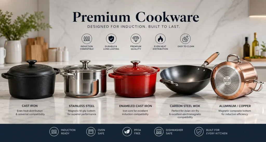
What Cookware Works on Induction? Compatibility Guide & Best Materials Explained
07/28/2026

Best Commercial Induction Cooktop for Restaurant: Types, Specs & Buying Guide (2026)
07/26/2026
How to Open a Hot Pot Restaurant in a Mall: Fire Code, Equipment & No Open Flame Solutions
07/24/2026
Gas vs Induction Cooktop: Energy Efficiency, Running Costs & Real Performance Compared
07/21/2026
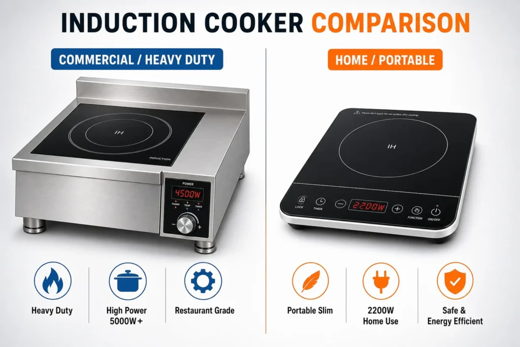
Commercial vs Home Induction Cooktop: What’s the Difference
07/18/2026
Induction vs Ceramic Cooktop: Key Differences in Heating, Efficiency & Safety
07/15/2026
High-End Commercial Induction Cooker: What Makes It Premium and How to Choose the Right One
07/12/2026
Industrial Induction Wok Burners (15 kW–30 kW): How They Differ from Standard Commercial Models
07/07/2026
Commercial Induction Wok Burners: Countertop vs. Built-In vs. Freestanding — Which Fits Your Kitchen layout?
07/06/2026
Commercial Induction Wok Range: What to Cook at Every Power Level (3.5 kW–30 kW)
07/05/2026